Monday, 13 January 2014

Scratchbuilding a US M2 Medium Tank in 28mm Part 5


Picture 21 Starting Suspension:  While the structures were being built, usually while the glue was drying, I gave some thought to the suspension.  Originally it was planned to phoney-up the running gear from some model tank parts.  Most of my stuff is 1/72 which is way too small for this project.  I had nothing suitable, and thought about maybe squash moulding some components.  Again following the drawings, I used some Evergreen tube to plot out some bogies.  The Evergreen tube is available in nesting sizes so thicker walled tubes can be built up.  Here a driver on the right and a bogie assembly are set out on some scrap plastic card.


Picture 22 Suspension Elements:  A star shaped drive gear was cut from plastic sheet.  These are the parts for the bogies, return wheels and drivers.

Picture 23 Bogie Details:  A block of thick plastic forms the mount and a thinner Evergreen tube makes the return roller. 

Picture 23A Bogie Details:  Further details added.  The bolt heads are Grandt Line or Tichy Train model railroad bits.  Note the green stuff to fill in the gaps.  The spokes of the bogies will be filled in with green stuff and details added to the face plate and the swing arms with thin plastic rod.

Picture 24 Alumilite Components:  A series of latex moulds were then made and parts cast out of Alumilite.  The latex brushes on in many coats and is reinforced with cheesecloth.  Shown are castings of the bogie unit and a return wheel.  Since twelve bogie units were required, two moulds were made of the bogie unit.  A simplified drive gear was also made and moulded.

Picture 25 Assembling Suspension:  Support plates for the suspension were drawn out and drilled. The backs of the Alumilite castings were also drilled.

Picture 25A Assembling Suspension:  Since I wasn’t sure how well the castings would adhere to the plastic; the drilled holes were to act as rivets when epoxy glue was used to assemble the components. The back view of the suspension plates shows the epoxy “rivets”.


Picture 26 Suspension Left and Right:  The assembled suspension sides cut apart.  Make sure you have left and right sides.  There were a lot of air bubbles in the Alumilite parts.  Some filler and some terrain-mud will resolve any issues.

Picture 27 Trackwork:  The suspension plates were then trimmed to size and sanded for the curves.  The plates will also be trimmed to show track sag over the return rollers.
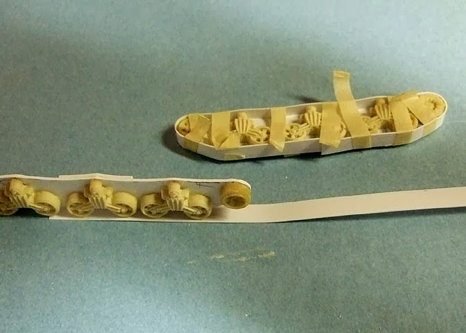


Picture 27A Trackwork:  Evergreen strip plastic was formed over the track side plates.  The liquid solvent glue holds the strip to the side plate.  A bit of Crazy Glue bonded the track strip to the bogies.  Liberal use of masking tape strips hold the strip in place until the glue dries.

Picture 27B Trackwork:  Inside view.  Note reinforcement strips top and bottom to hold the track strip in place.  Spacer blocks will hold the track assembly to the lower hull.

Picture 27C Trackwork:  Two assembled track units.  At this point I was looking at many, many hours gluing many, many small strips of plastic to create the track links.  Staring forlornly at my stock plastic box I came up with an alternative. (Remember that part about the only person you have to please is yourself and personal choices about how much work you want to do and how much detail you want to add?)

Picture 28 Track Details:  I had some formed plastic roof tiles that had a suitable “bump” for the track links.

Monday, 6 January 2014

Scratchbuilding a US M2 Medium Tank in 28mm Part 4


Picture 15 Planning Turrets:  The basic octagonal box structure was repeated for two turrets.  Note the top panel of the turret is sloped down at the front so top and bottom of the turrets are not identical.  This is structure, so thick plastic again.


Picture 16 Assembling Turrets:  Assembling the turrets.  Note the spacer to establish the height of the turret and that the front spacer slopes down to the front.


Picture 17 Plating Turrets:  Thinner plastic card is used to skin the turrets.


Picture 18 Basic Turrets:  The basic turrets.  A thicker plastic sheet will be used for the front plate of the turret.


Picture 19 Tubes and Cylinders:  A second structural element is round-section tubes.  Four machine gun turrets are required on each vehicle.  Here, suitable diameter Evergreen tube is capped with thin sheet.  When thoroughly dry, the cap can be trimmed and sanded to match the outside diameter of the tube.  The tube is cut to length and the open end capped, trimmed and sanded.  The capped tubes are then sliced vertically into halves.


Picture 20 Taking Shape:  The machine gun turrets are added to the crew compartment.  A plastic tube was added to the turrets to form a pivot.  Also added was a disk to the bottom of the turret to allow it to turn freely.  Some small similar thickness spacers were later added to the bottom of the turrets to eliminate wobble.  The upside down turret has a thick front plate added and has yet to be trimmed.  Note how the hull’s base plate will form the front fenders and rides above the area the tracks will run.


Picture 20A Taking Shape:  Top and rear view of the basic structures.  At this point, other than the tubes for the machine guns, there have been no curved structures.  This complex shape is built up with layers of flat sheet. 

Scratchbuilding a US M2 Medium Tank in 28mm Part 3


Picture 8 Drivers Compartment:  Here we start fitting some of the skins for the driver’s compartment. The front section forms a pyramid structure. Two sets of drawings I had did not match and one showed a “cheater” plate to fill the driver’s compartment and the crew compartment. Notice how the back of angular plate, the side plate of the driver’s compartment, does not meet with the line on the crew compartment.


Picture 8A Drivers Compartment:  This becomes more apparent when skinning in the upper sides of the driver’s compartment and the purpose of the “cheater” plate becomes apparent.  Note the gap between the upper and lower plates of the driver’s compartment.   The lowest glacis plate is also installed and can be trimmed to size and edges filed to shape.

Picture 9 Cheater Plate:  The “cheater” in blue, fills this area.  This is not obvious in the drawings, but is clearly visible on photos of the real vehicle.  The pyramid structure of the driver’s compartment is not true pyramid.  In this case, as the model progresses, the model itself will direct how it is to be built.  Note too that overlapping plates can be installed on the inner edges, and the overlaps can later be trimmed to size.


Picture 10 Lower Rear:  The lower rear, showing the floor plate. Note the lower rear is actually two plates so the side plates and rear base plate need to be trimmed.


Picture 11 Trimming the Rear Deck:  Here a razor saw aligned with the trimmed lower side plates will be used to bob the vehicle’s rear end to the correct angle.


Picture 12 Filling in Rear Deck:  The upper rear decked in.  Note the use of thick and thin for structure and for sizing.  You sometimes have to recess one part to set in an additional panel or make a part out of thicker stock to come up to the correct measurements.  Generally structure is thicker than ‘skin’.  The rears of the upper and lower sections are now at the correct angle.  The lower side plates are yet to be trimmed to the correct angle for the lowest rear plate.


Picture 13 Basic Hulls:  The “basic” hulls.


Picture 14 Basic Hulls:  Side and rear of two basic hulls.


Picture 14A Basic Hulls:  Here I took my Dremel to the floor and up thru the base plate.  I had planned to add some weight to the models.  This also gave access to the interior structure if required later.  Ultimately neither the weight nor the access was used. 

Friday, 3 January 2014

Scratchbuilding a US M2 Medium Tank in 28mm Part 2

For the M2 model the plane just above the tracks is a good starting point.  I began with a rectangle of plastic the width of the model but longer than that required.  I will build the tank’s upper works on top of this plate, and the lower works on the bottom of this plate.  This plate forms the foundation of the model, so make it out of heavy stock, in this case, 40 thou sheet.


Picture 1 Starting Point:   Shows the base plate. It is probably as easy to build two models as to build one, so construction was started on two vehicles.  Also shown here is the upper deck.
The upper deck was scaled off the drawings and drawn out straight onto the plastic sheet. Since the turret will mount on this deck, it and the spacers supporting it, were cut from the heavier 40 thou sheet.

Picture 1A Turret Deck:  This shows the upper deck plate. Note the arrow and the correction in the upper right corner.   While the basic rule is measure twice, cut once, most things can be corrected as the project moves along.

Picture 2 Assembly One:    Shows a “front view” of the basic assembly.  I use Testors liquid Plastic Cement for the styrene parts.  The forward part of the base plate is much longer than required; it will be trimmed in following steps.

Picture 3 Plans on Materials:   Since we have scale drawings, parts can be measured on the drawings and transferred to your stock.  This is the left and right sides for the rear of the vehicles and since this is ‘skin’ and not structure, it is lighter 20 thou plastic card.  Two vehicles: so two lefts and two rights, two ups and two downs, as the depth of the rear structure is not half way!  Keep your left/right and up down spacing correct.  Laying them out as a group ensures equal measurements.  Note the double line where a measurement was checked and corrected.  The trick then is to remember which line to cut.  If a piece is miss cut, it is usually best to discard it and cut again, rather than fiddling to fix it.


Picture 4 Side Plates:  Here we start to “skin” in the upper structure.  The ‘octagonal’ crew compartment is skinned in and the side panels are mounted.  Note the reinforcement bit on the upper right.  Try to get a tight corner along the edge of the base plate.  Notice too, the side plate sits on top of the base plate but the top plate is inside the side bit.  Basically the purpose of the base plate is also to preserve the dimensions of the vehicle, providing a straight line from the front fenders to the side plates.

Picture 5 Lower Hull:  Here, side plates for the lower hull are sketched out.  These side plates will support the tracks so they are also heavy stock.

Picture 6 Lower Hull Two:  The model itself forms part of your building plans.  The underside of the base plate is marked for a centre line and the position of the lower side plates.  A line across the vehicle marks the rear edge of the crew compartment and references measurements front to back.

Picture 7 Lower Hull Three:  This photo shows the lower hull plates assembled with a rectangular lower plate.  Also installed is a lower glacis plate, and part of the “pyramid”.  Using a top view of the drawing the width of the pyramid plate at the upper glacis can be determined. The length of the angled plate can be taken from a side view of the vehicle. -At this point, you are into the world of ‘as-builts” if your model is not to the scale or size you want, it is probably best to start over before you do too much work.  Otherwise, use the model to determine the dimensions of the parts.  It is as you built it.  The width of the front glacis is the width measured on the model.  What I have done here is trim the front portion of the base plate to leave the front fenders sticking out. I then trim the plate to allow the front glacis to assume its natural angle.  It will be very close to the drawing and it’s up to you how close you need it to be.  For me, this is close enough.

Wednesday, 1 January 2014

Scratchbuilding a US M2 Medium Tank in 28mm Part 1


One of my wargaming buddies is deeply involved in gaming the Very British Civil War in 28s.  In order to participate I looked at potential foreign contingents.  I though possibly a US ‘Abraham Lincoln Brigade’ might be appropriate.  I began then to look into tanks for support and found some references to the M2 Medium.  It literally bristles with machine guns and has very VBCW flavour.  Built in 1939 it is just on the fringe of the time frame, but I felt it would be close enough.
Begin this (or any project) with some basic research.  A Google search for “M2 Medium Tank” or “M2 Medium Tank drawings” turns up a variety of photos and drawings.  Two useful sites are:

I downloaded some three- views and some detail photos.  Using the basic dimensions of the vehicle I was able to print out some scale plans.  Calculating to roughly 1/56 scale you may be able to use your home printer to print at a percentage reduction.  Alternately print out your drawings, measure and calculate a reduction or increase and have your local photo-copy store reduce or enlarge as needed. I usually print out a couple of sheets of the scale drawings to take measurements on and at times to cut up for full-size templates.
Some basic drafting skills may be required, but with the scaled drawing you can measure directly on the drawings to size up your stock.  (More as we continue.)
I used 40 thou Evergreen white styrene sheet for strength in the support structure, and generally “skinned” with thinner 20 thou stock.  The 20 thou is thin enough you usually do not have to account for the thickness.  Using thicker stock will make a stronger model, but remember to compensate for the thickness of the materials in your measurements.
My basic tools are a steel rule and a snap blade hobby knife.  The Evergreen styrene card is easily scored and snapped or can be trimmed with a sharp knife blade.  The steel rule provides a straight edge for cutting and is graduated down to 1/64th of an inch for measuring.  I can’t see or mark out a measurement smaller than 1/64 and for a wargames’ model that is sufficient tolerance.  You only have to make yourself happy so work to whatever tolerances you prefer, add details and be as accurate as you wish.  The best advice I can give is to be patient, and let the glue dry.  When in doubt let an assembly dry thoroughly overnight before you try to proceed to the next step.
I also did some Alumilite castings in latex moulds and some “squash” moulding for complex parts.
Any structure is can generally be thought of as a series of boxes of various shapes and angles, tubes, and some complex shapes.  The M2 is mostly flat plates and I will demonstrate some methods to build complex looking shapes out of easily obtainable materials.  The driver’s compartment is an interesting pyramid shape, which is rather confusing in the drawings, but since the real vehicle was built out of flat plates, progressing with a model will reveal what the drawings do not.

Sunday, 20 October 2013

Fun with foam

I started building up the works between the guns rather like the hills between the positions at Fort Fisher. Since I have three gun positiions, the left flank will have a hill attached and the right will have a small hill section that can be set next to one, two or three sections of the gun positions.


The transition between two sections is formed of two layers of the pink foam, and will be faced with card cut to an exact profile.  This will allow the sections to be placed next to each other in random order with a smooth transition from one to the next.  The foam here has been rough cut with a utility knife and hot glued in place.  Once the hills have been "bulked-out" in foam I will take my hot-wire cutter to do the basic contours, followed by a 'surform' tool and some filler.

((I am finding Blogger to be annoyingly un-coperative these days. I am due for a computer upgrade, and perhaps a new OS and and maybe Chrome will sort it out.))

Sunday, 6 October 2013

Progress on the guns!

Finally have some progress on the HBG gun carriages and gun positions.  The barrels have been cast in Alumlite.  See the previous post or my flickr page for the details of the mould.  Not the best or highest tech mould making, but I got a couple guns out of it to use.  The brown spots are Tichy Train Group rivets, drilled and glued into place. I have a little do-dad for each gun for the elevating mechanism.


When I was building the carriages I made a flat out of art board to set the various elevations of the platform. The pivot was the highest and there are two steps for the runners and the wheels.  Here I began work on a gun position. There will be three gun platforms, with sand/turf hills between each rather like the land wall at Fort Fisher.


So lots of work to do yet!